
Design Constraints & Initial Conditions
I use a filament dry boxes equipped with a transversely mounted 8 mm steel rod. My setup accommodates various filament spools with inner hub diameters ranging from 50 mm to 78 mm and spool widths from 35 mm to 90 mm. The bore holes can be either smooth or flanged.
I needed an adapter that could fit into any of these spool hub variants. The adapter had to be universal or easily adjustable. Furthermore, it could not protrude significantly from the spool hub, as I stacked multiple spools inline on the rod inside a space-constrained dry box. The adapter had to be lightweight while maintaining optimal compliance. Once assembled, the adapter and spool mechanism had to be robust enough to withstand shocks and impacts during dry box handling without coming apart.
Concept Selection
A single-piece fixed or spiral design was quickly ruled out; it fails to reliably cover the wide 50 mm to 78 mm bore range. It would be too difficult to insert into smaller hubs and lacks sufficient structural stability in larger ones.
A conical/tapered design was also rejected because it takes up too much clearance outside the spool face, making it unsuitable for stacking multiple spools sequentially on a single axle.
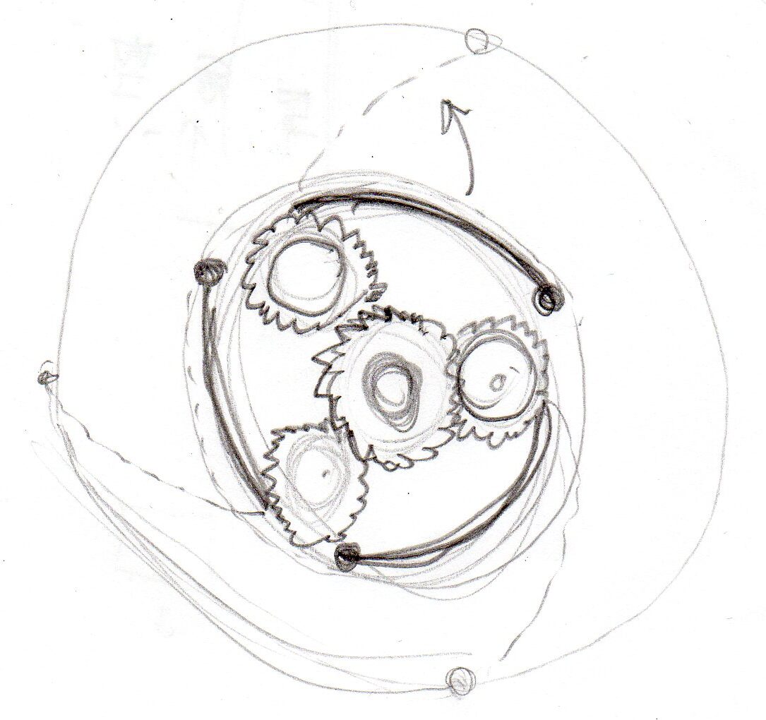
The initial concept sketch shaped up roughly like this.
Next came the dimensional verification stage, which involved:
- Verifying the adjustment range, arm clearance, and sizing constraints.
- Designing the main chassis/frame to fit within the smallest hub opening while ensuring the compliance arms retain spring tension at minimum settings.
- Optimizing the adapter height to seamlessly accommodate standard bolt and hex nut sizes from my inventory 🙂 .
Design parameters and validation
Design validation was tailored for additive manufacturing (3D printing optimization):
- Determining the minimum gear module/pitch that can be printed reliably while maintaining sufficient mechanical strength.
- Determining the maximum gear diameter relative to the smallest spool bore.
- Selecting the number and type of gears required to achieve the desired adjustment increments.
- Establishing the proper clearance between gears.
- Defining the minimum wall thickness for slicing.
- Optimizing the arm thickness based on the intended spring-loaded deflection.
- Formatting the arm geometry to preserve structural compliance and elasticity.
- Implementing threaded features (either a standard metric nut pocket or a brass heat-set insert).
- Specifying XYZ dimensional tolerances based on the joint characteristics (fixed vs. dynamic fits, plastic-on-plastic, plastic-on-metal, plastic-to-nut, or plastic-to-screw interfaces).
- Engineering the contact profile where the arm interfaces with the inner spool hub.
- Determining the thickness and height of the retention lip/flange on the arm’s contact interface.
Features
- Delamination Prevention: The compliant spring arm is designed so that the 3D-printed layers undergo compression rather than tension during flexing, preserving elasticity and preventing structural failure or layer splitting.
- Dual-S Curve Geometry: Enhancing compliance and reducing material fatigue by introducing a double-S curve geometry.
- Lead-in Chamfer: Adding a bevel on top of the arm to facilitate easier insertion into the spool hub.
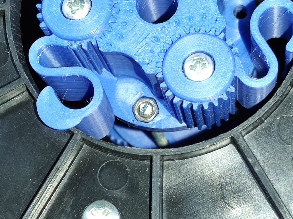
- Captive Hardware: Allocating a recess for a captive nut and a pass-through clearance hole for cross-fastening.
- Optimized Retraction: Determining the optimal fully retracted position.
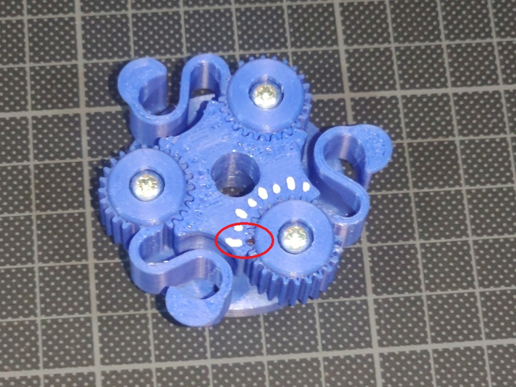
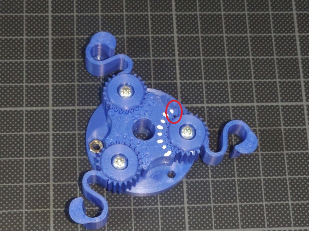
- Visual Indexing: Integrating position markers, logo placement, and finger grips on the position-locking mechanism.
- Tool: Tool works both ways. <iit acts as a push-out tool for disassembly and as an alignment/centering jig when securing the locking piece.
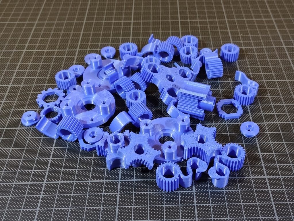
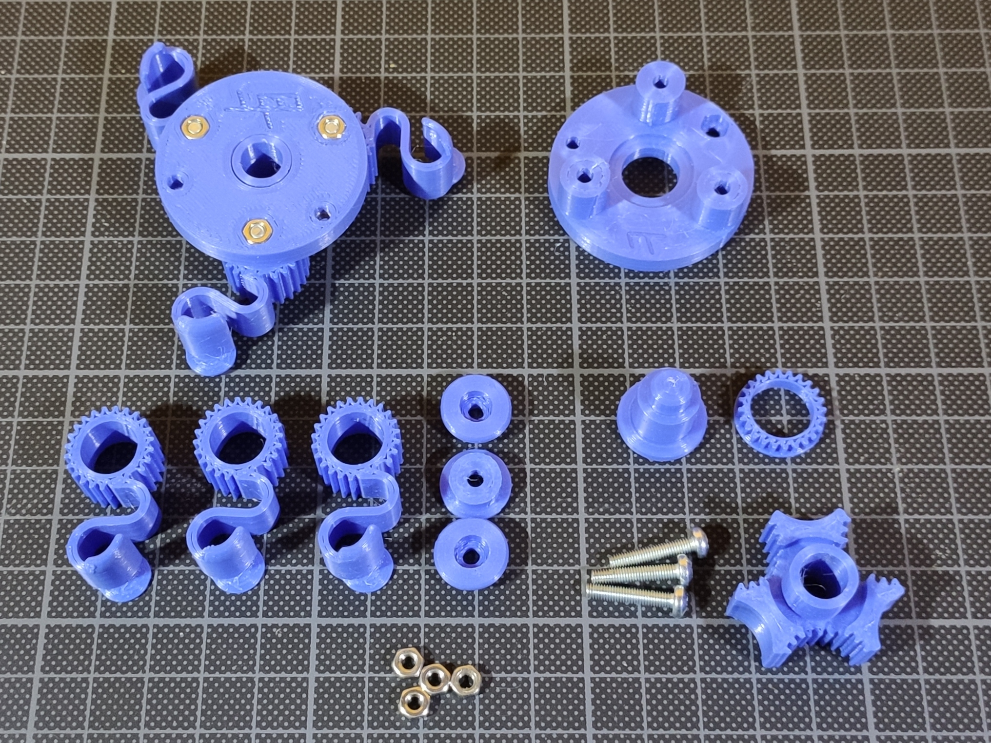
After a week of R&D, rapid prototyping, and a few failed test prints, here is the final low-profile iteration.
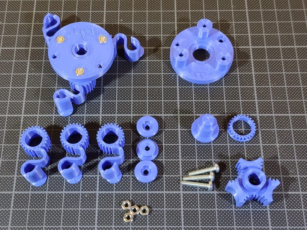
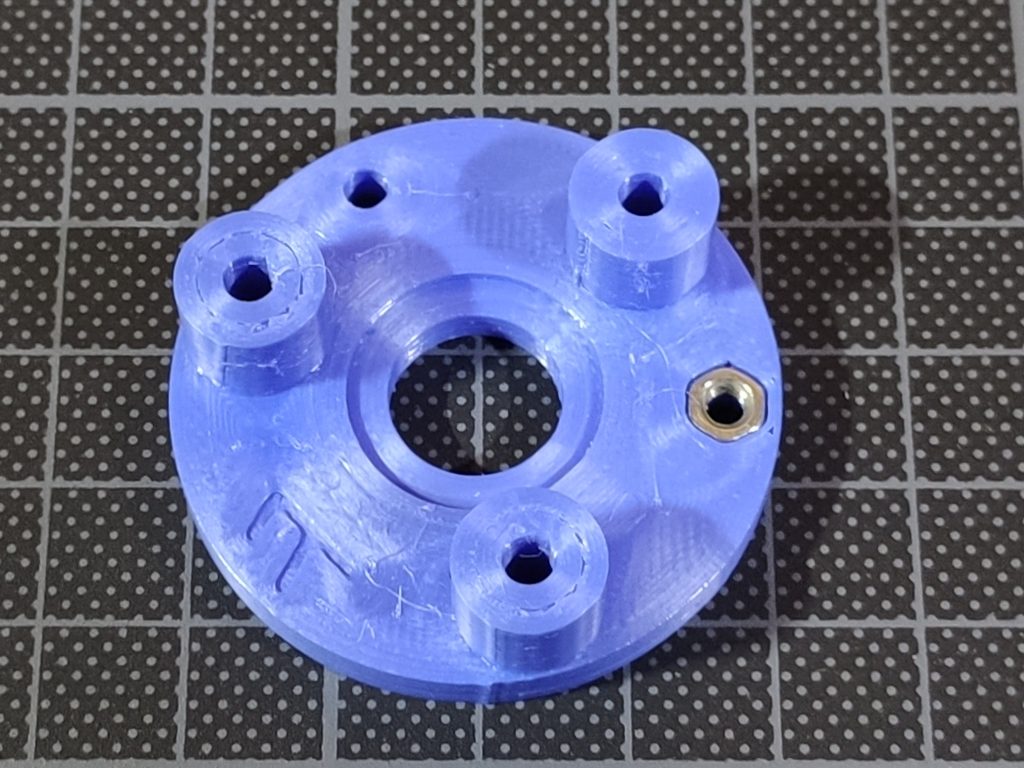
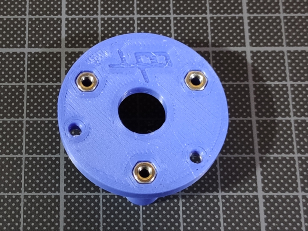
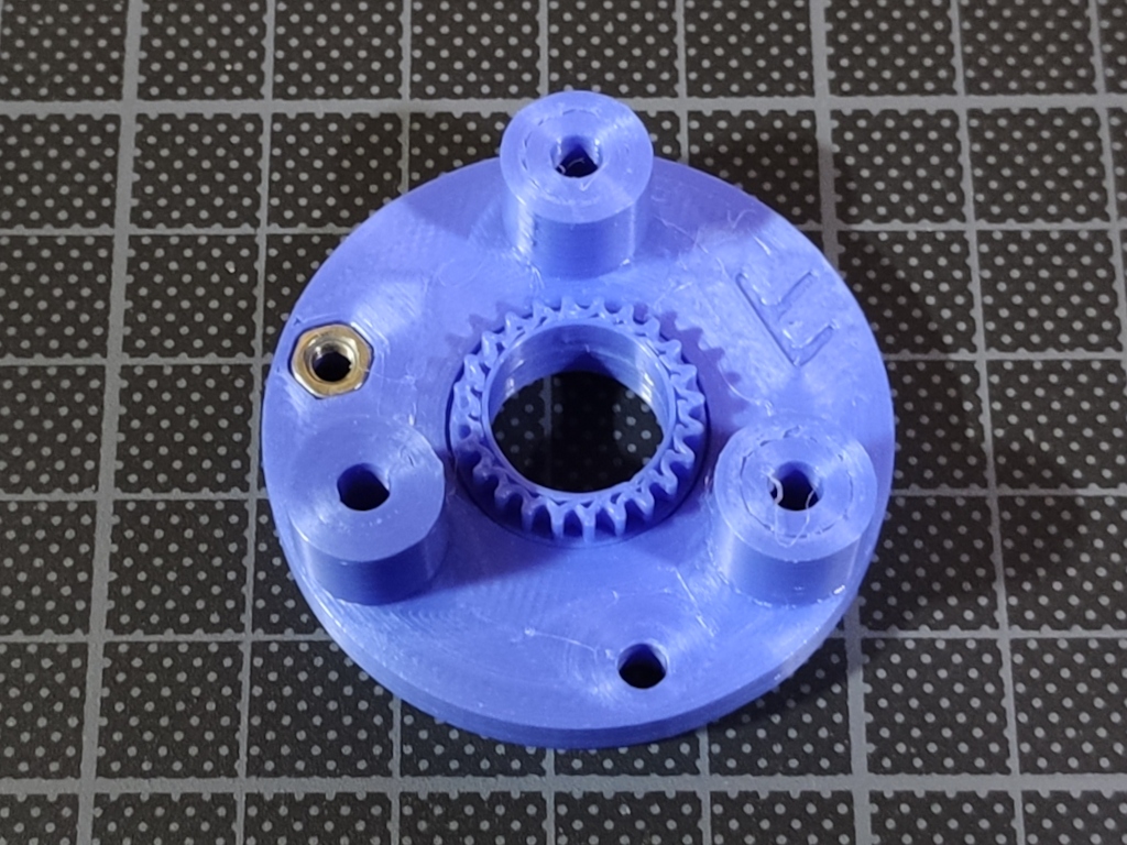
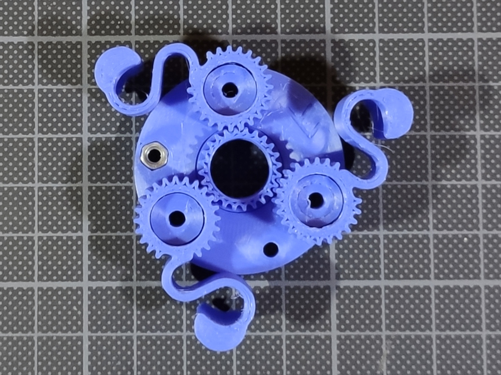
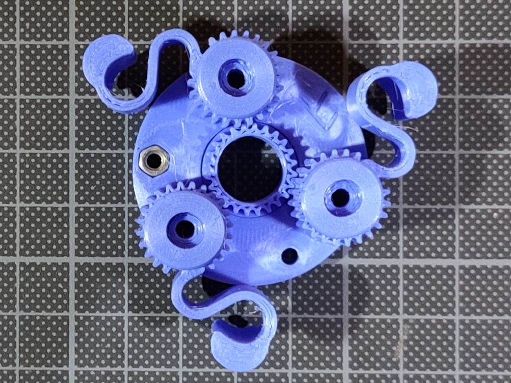
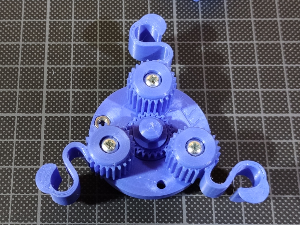
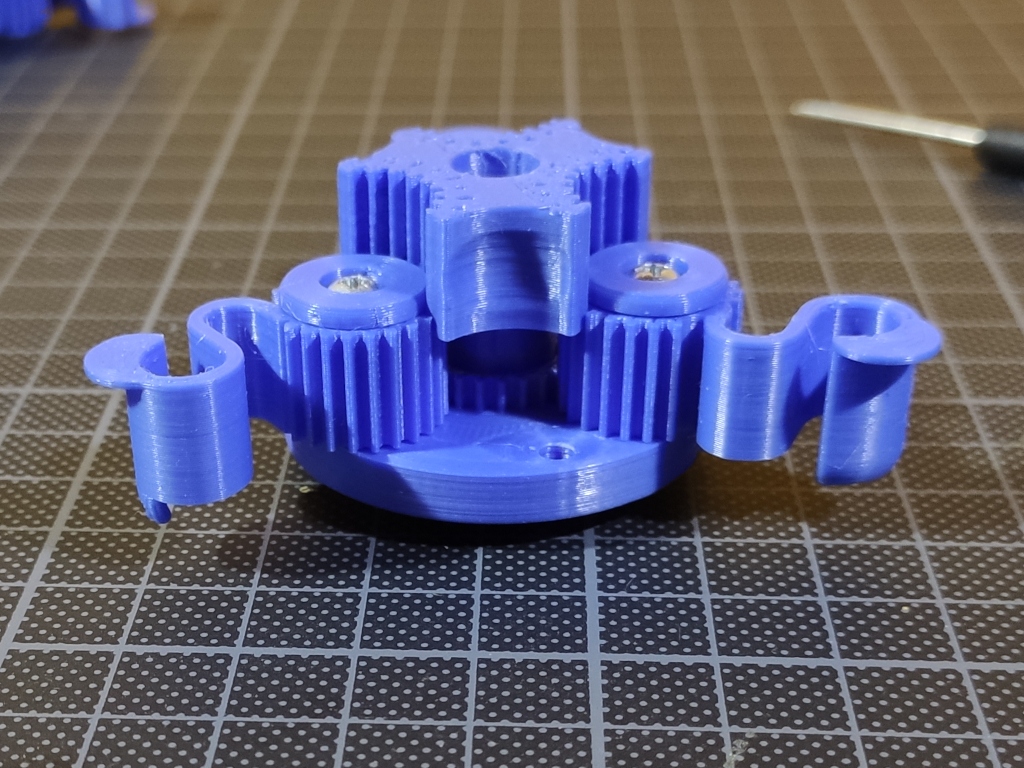
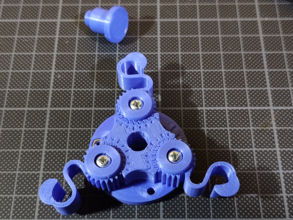
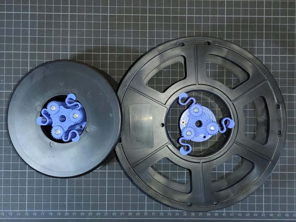
The two complementary adapters are secured together using a machine screw to prevent the assembly from collapsing under lateral impacts. The linking screw does not require an exact length; it just needs to fall within the engagement range of the captive nut, allowing a +10 mm tolerance before bottoming out or causing interference on the opposite side. Alternatively, zip ties, wire, or other fasteners can be fed through the cross-holes. A screw is shown in the image as it is the easiest option to self-center over longer distances.
The indexing marks on the position-locking component are designed to be highlighted with paint or a permanent marker to create a highly visible scale. To act as a pointer on the moving compliance arm, you can either clip the tip of a gear tooth at its minimum position or color it with a permanent marker. This creates a high-contrast indicator for easier diameter calibration.
Printing Tips
- Isolate Ironed Components: Print the base piece independently from other parts if you enable the ironing top-surface feature.
- Mitigate Thermal Defects: Printing adjacent parts simultaneously on the same build plate with ironing active can introduce cosmetic defects or dimensional inaccuracies. This is caused by localized thermal expansion during the long ironing pass or uneven part cooling immediately after completion.
Fasteners
M3 nuts, M3/16 screw for thinner version and M3/25 screw for thicker version.
You can download both versions for free here if you have a Creality account :
Filament Spool adjustable centering hub. STL & 3MF File for 3D Printing | Other | Creality Cloud
Or direct download:
https://drive.google.com/file/d/1cpnRRnWKH2Fq8A71PDghdKU6DJOv26vg/view?usp=sharing
https://drive.google.com/file/d/1V4pP3pOIg0pXjjaRPnaJ7JIm1YF-qlPN/view?usp=sharing
Also short Youtube clips about adjusting